Wednesday, 28 December 2022

Find Out About Plastics - My End-Of-The-Year Review 2022 and Outlook 2023

Find Out About Plastics - My End-Of-The-Year Review 2022 and Outlook 2023

Hello and welcome to my end-of-the-year review 2022 and outlook for 2023. I walk you through this year and touch briefly on all published posts. 

January

In January we kicked off the blog year with an overview and definitions of sustainability in the Plastics Industry. Biron [1] identified six major areas to put the focus on when implementing a sustainability concept and creating a sustainability concept is a step-by-step progress toward the best possible sustainability in your company. We had a guest interview with Mr. Max Funck from specialty compounder PlastFormance. We learned about their highly filled compounds to enhance high conductivity (thermal, electrical) and radiation shielding. Also in January we discussed some major trends to watch for in the chemical industry and continued with the Global Warming Potential (GWP) of thermoplastics. I showed the GWP values of thermoplastics compared to their different thermal properties and transitions: Tg, heat capacity (Cp), short term temperature exposure (HDT) and long term temperature exposure (UL Yellow Card). This allows for a better assessment of the different GWP values in relation to the resin properties.

Read all  posts of January 2022 here 

February

In February I wrote three posts on design properties for plastics engineering: Key Electrical Properties of Selected Engineering and High Performance Polymers for E-Mobility, Selected Properties of Natural Fiber Based Polymer Compounds, and Mechanical properties of PCR, PIR, bio-based, and mass balanced plastics. Apart from the engineering data post, we discussed blockchain technology as an enabler for tracing recycling content of plastic compounds and cascade recycling as a possible way forward for plastics processing companies to ensure a proper tracing of the used polymers. In another post I picked up the six strategic principles of Mark McNeilly’s book “Sun Tzu and the art of business” and tried to apply them in today’s VUCA (volatility, uncertainty, complexity, and ambiguity) plastics world. Another more hands-on post was a simple tool for calculating the residence time for extrusion operations. 

Read all  posts of February 2022 here

March

In March we discussed three considerations for optimal dimensional stability of plastics parts after processing. Polymer based parts have a dimensional stability which is not equal to that of metals. It can vary with several factors which we discuss in the following in more detail. If it is a critical part, this needs to be considered during the polymer material selection. Also we discussed an operational life-hack. We looked at a well-known cognitive bias that psychologists refer to as “survivorship bias” and how to use this information for better decision making in our daily plastics operation. Biopolymers were a topic in March too. I showed how you can use the 3P (price, performance, and processing)-triangle to select engineering biopolymers. In addition, we discussed three topics under the sustainability umbrella: bio sourcing, LCA, and certifications.

Read all  posts of March 2022 here

April

In the month of April we discussed the DMA data of unfilled engineering polymers as well as reinforced engineering polymers. In general, the DMA is a thermo-analytical method that estimates the viscoelastic properties of a given material over the course of different temperatures. It steps away from a single point view toward a multipoint data view which is beneficial for polymer material selection tasks. Another topic was how to optimize the wall thickness of well- known PET bottles by using safety factors and the stress equations.

Read all  posts of April 2022 here

May

In May I presented 6 major benefits of injection moulding simulation in polymer part design and material selection. In addition we discussed the water and moisture uptake of aliphatic short and long chain Polyamides as part of our “Plastic Part Design Properties for Engineers” series. In May we discussed the penguin circle which stands as a symbol for teamwork and leadership.

Read all  posts of April 2022 here

June

In June, right before the summer, I presented the second episode of my Ocean Plastics - What The Media, NGOs and Others Still Not Tell You series. In Episode 2 we discussed all kinds of waste dumping and that the "out of sight, out of mind” attitude for dumping waste into our ocean is wrong. Also, blaming plastics to be the number one littering source for our oceans is wrong too. The data speaks a clear language. There is more and more ideological thinking involved in such anti-plastics topics and too less decision making based on facts. Plastics are part of our solution and are not the problem. Another topic in May was on the topic of flame retardants, starting with an overview and then discussing as an example effective flame retardants for Polyamides. In June I presented a summary of testing standards which is helpful in the material screening phase during polymer selection for your application to have a feeling which tests can be done and what standards are linked to them. Furthermore we discussed the HDT (1.82 MPa) of filled and unfilled amorphous and semi-crystalline polymers as part of the “plastic part design properties” series. 

Read all  posts of June 2022 here

July

In July we discussed what are the PTFE free alternatives for lubrication in friction and wear compounds. In conclusion, from an polymer material selection point of view, UHMW-PE is an alternative material for applications that need excellent sliding properties as well as excellent wear resistance. Furthermore, flame retardant properties can be achieved by mixing UHMW-PE (wt 80%) with PTFE (wt 20%). Another post focused on highly filled PP compounds as enabler materials for improved flame retardancy, cost, and functionality. Third topic in July was the CLTE of commodity polymers, mineral fillers and metals with the focus on how to control CLTE in an optimal way.

Read all  posts of July 2022 here

August

In August I gave you an update on my HDPE plastic bag degradation experiment. This summer I spent some weeks in our apartment flat in Sesimbra, Portugal which by the way you can rent for your holiday as well.  I used this time to check on my experiment which I started in January 2021. Furthermore I wrote three “Plastic Multipoint Design Data” posts : Specific Heat Capacity as a Function of Temperature, CLTE of Polymers as a Function of Temperature, and Thermal Conductivity of Polymers as a Function of Temperature. In August we discussed the starting point in polymer material selection. In general there are several procedures for material selection such as the Ashby methodology or my own developed funnel approach. However, all the selection processes and procedures should have the definition of the part requirements as their common starting point.

Read all  posts of August 2022 here

September

In September we discussed ways to increase the Comparative Tracking Index (CTI) of thermoplastics. In general, there are polymers which more likely form a conducting carbonized path compared to other polymers. Aliphatic and semi-aromatic polymers, polyolefins, fluoropolymers, as well as polyesters show high resistance to form a conductive carbonized path. PPS on the other hand more likely forms a conducting carbonized path, combined with a low tracking resistance. Also I presented an effective way to turn thermoplastics carbon neutral or even carbon negative. In another post we uncovered the flame retardant classification according to DIN EN ISO 1043-4. In September we answered a community question on what should be the minimum transparency level required for plastic laser welding. In general, thermoplastics transmit a near-IR beam. The upper plastics layer needs to have transparency for wavelengths between 808 nm – 1064 nm. A minimum transmission rate of 5% is required, however optimal would be 30% and greater.

Read all  posts of September 2022 here

October

In October I started the three part series on the important role of additives (Part 1 and 2). They enhance polymer properties for high performance applications. Furthermore I showed the processing considerations of PBT and its crystallization behavior.

Read all  posts of October 2022 here

November

In November we discussed the injection molding of polymers with flame retardant (FR) and how the flow and chemical resistance of amorphous polymers can be improved. In addition I presented an overview of the chemical resistance of commodity and engineering polymers. Furthermore I showed another important multipoint and long-term data set for polymer material selection and part design: tensile creep modulus.

Read all  posts of November 2022 here

December

In December I presented the third part of our plastic additives series. In this post we discussed how to improve the conductivity (thermal and electrical) of polymers by using different filler systems. Also we discussed another set of multi-point design data: the brittleness as a function of temperature for amorphous and semi-crystalline thermoplastics.

Read all  posts of December 2022 here

Hello 2023

In 2023, I will continue to present posts which evolve around 3 main categories:

- Polymer material selection and applying the Polymer Selection Funnel. I aim to present on a monthly basis a selection example using my funnel methodology.

- Design properties and multi-point data for engineers (incl. eco-design for sustainability in plastics) as well as design of materials using compounding and additives.

- Leadership and strategy in plastics industry

Furthermore, I invite you all to leave topics you would like to read about in 2023 in the comment box below or leave me a short message here.

I am working to publish my “Pumping Plastics” monthly newsletter as a book in 2023. More details will follow. 

Last but not least, I would like to thank all readers of my posts!!!

I hope to welcome you again next year.

I wish you happy holidays and a very happy New Year 2023!

Thank you and #findoutaboutplastics,

Greetings,

Herwig Juster

*NEW* my Polymer Material Selection book is out - get a copy here


Saturday, 24 December 2022

Seasons Greetings 2022

Hello community, 

I wish all my readers a safe and happy holiday season!

Soon my annual review incl. best of 2022 as well as outlook for 2023 will be online.

Greetings and #findoutaboutplastics

Herwig

Season Greetings 2022


*NEW* my Polymer Material Selection book is out - get a copy here

Monday, 19 December 2022

The Important Role of Additives: Enhancing Polymer Properties for High Performance Applications (Part 3)

Hello and welcome to the third part of our plastic additives series. In this post we discuss how to improve the conductivity (thermal and electrical) of polymers by using different filler systems. 

 Here you can read part 1 and here part 2

Volume vs weight of fillers

Before we deep-dive, let us clarify an important consideration: volume vs. weight of fillers. For formulating a plastic compound, understanding the volume fraction is key. For compounding we need to translate it to a weight based unit, since it is easiest for the extrusion process to set a weight unit and not volume. 

Key is to plot your compound properties as a function of volume percent and not weight percent. It will result in straight lines and not exponential as with weight percentage. Figure 1 shows a PP loaded with different fillers and the filler level is expressed over the volume percentage [1]. 

Figure 1: thermal conductivity of PP and different fillers as a function of filler volume % [1].

Thermal conductivity of metals, carbon, and ceramics

Before we compare specific fillers used in plastic compounds to increase the thermal conductivity, we have a look at the thermal conductivity of selected metals, carbon, and ceramics (Table 1). This allows us to get a first feeling for the different thermal conductivity levels, together with the densities. 

Table 1: overview thermal conductivity of selected metals, carbon, and ceramics

Electrically conductive and non-conductive fillers for plastic compounds

If you are confronted with the task to improve the thermal conductivity of your polymer, Table 2 can serve as a starting point. If one of the requirements during material selection is to fulfill a certain thermal conductive level, optimal fillers are key. Ceramic based fillers such as Boron nitrite show a high thermal conductivity, however due to the plate shape, it is high in plane direction and lower through plane. Spheric fillers allow for a more uniform conductivity in the final plastic part. 

Table 2: electrically conductive and non-conductive fillers for plastic compounds.

Check out part 1 and here part 2 too. 

Thanks for reading and #findoutaboutplastics

Greetings, 

Herwig 

Interested to talk with me about your polymer material selection, sustainability, and part design needs - here you can contact me 

*NEW* my Polymer Material Selection book is available for purchase here *NEW*

Interested in my monthly blog posts – then subscribe here and receive my high performance polymers knowledge matrix.

Literature: 

[1]  https://phantomplastics.com/plastic-materials-training-from-a-top-expert/learn-about-filled-plastics/

[2] Gächter and Müller: Plastics Additives


Sunday, 18 December 2022

BIG Day Today - My Polymer Material Selection Book is available for purchase on Amazon!


Dear community,

It's a magical feeling to hit the button on Amazon to publish my book and it is now live! 

Allover it was a great experience to go through the whole process of writing and self-publishing. 

The digital version is now available for Kindle, Tablets and Laptops and the paperback version is coming soon.

I hope that in the next days Santa Amazon will bring me my proof copy so I can release it.

If you get a copy, please let me know what you think. You can send your comments either directly to me, or leave a review on the publishers website, also via the link above.

Let's do it - Get your copy here

Enjoy the read!

Greetings and #findoutaboutplastics

Herwig 

My new Polymer Material Selection book is now available!


Monday, 5 December 2022

Plastic Multipoint Design Data: Brittleness as a Function of Temperature

Hello and welcome to a new post. Today we discuss another set of multi-point design data: the brittleness as a function of temperature for amorphous and semi-crystalline thermoplastics.

In general, the impact strength of thermoplastics is highly dependent on the testing temperature. Brittle behavior, together with notch sensitivity, occurs mainly at lower temperatures. Figure 1 helps you during  material selection to reject certain polymers since they are not fulfilling the lowest service temperature of the application. 

Polycarbonate and Polyamide (conditioned) are able to withstand a break even when the specimens are sharply notched. PMMA on the other side shows over the whole temperature range a brittle behavior even when unnotched. 

Figure 1: brittleness as a function of temperature for amorphous and semi-crystalline thermoplastics [1]

More multi-point design data you can find here

Greetings and #findoutaboutplastics

Herwig 

Interested to talk with me about your polymer material selection, sustainability, and part design needs - here you can contact me 

Subscribe to my Polymer Material Selection book launch page 

Interested in my monthly blog posts – then subscribe here and receive my high performance polymers knowledge matrix.

Literature: 

[1] A.A. Collyer: A practical guide to the selection of high-temperature engineering thermoplastics, Elsevier, 1990


Tuesday, 22 November 2022

Injection Molding of Plastics with Flame Retardant - 10 Important Things to Consider

Hello and welcome to a new blog post. Today we discuss the injection molding of polymers with flame retardant (FR). In general, flame retardants are added to lower the flammability of the used polymer. There are three main classes of flame retardants: nitrogen-phosphorus systems, halogenated systems, and metal-hydroxide systems. They have different working mechanisms (chemical reactions; building up a protective layer; release water for cooling) and Table 1 summarizes the advantages and disadvantages of the different flame retardant systems. 

Table 1:  Comparison of the advantages and disadvantages of the different flame retardant systems

Furthermore, the standard ISO 1043-4 shows detailed classifications of different flame retardants.

High performance polymers which have a higher level of aromatic elements in their backbone need few or no additional flame retardant at all. They  reach inherently a UL94 V-0 flammability rating with the exceptions are PSU and semi-aromatic Nylons such as PPA and PARA which need additional flame retardants to reach V-0. 

Selecting the optimal flame retardant plastic grade during material selection is one thing, processing them by injection molding is another thing, especially when you use hot runner systems. 

It is important to keep the melt processing temperature below the decomposition temperature of the flame retardant. FR-based systems are lower processed than the base polymer used. Following the processing recommendations of the material supplier is important. Also to not increase unnecessarily the melt temperature through too much shearing. 

10 Important things to Consider for injection molding of FR-plastics

1. Usage of corrosion protected plasticizing unit, hot-runner and tool: some flame retardants are corrosive since they generate acids while reacting with water. Therefore, Polyamides should have a residual moisture of below 0.2%.

2. Limitations in residence time and melt temperature: FR-plastics have a 30-40% lower residence time compared to non-FR plastics. For example, a Polyamide with 25 weight-% glass fiber (Zytel 70G25) hs a residence time of 15 minutes, where else the FR-Polyamide with 25 weight-% glass fiber (Zytel FR 70G25 V0) has a residence time of 10 minutes. Furthermore, the preferred melt temperature shall be around 15°C lower compared to the corresponding non-FR reinforced grade. 

3. Design of tool and hot-runner: usage of naturally balanced hot-runner channels (flow length from injection nozzle to injection point)

4. Design of tool and hot-runner:  usage of thermal separation is important (hot-runner with melt temperature level and tool is cooled). 

5. Design of tool and hot-runner: heating should be casted in and not only be inlaid.  This ensures a better heat transfer. 

6. Design of tool and hot-runner: enable a uniform temperature system of the hot runner by symmetric heating

7. Design of tool and hot-runner: prevent dead corners in the hot runner by using separator inserts (redirection of melt). 

8. Design of tool and hot-runner: make the hot runner nozzles interchangeable in case wear is damaging the nozzles. 

9. Design of tool and hot-runner: consider good thermal separation in the nozzle area. Otherwise local high temperatures lead to a reaction of the flame retardant. 

10. Design of tool and hot-runner: usage of temperature sensors with PID capability (photoionization detector) to optimally control temperatures of each runner nozzle. 

Conclusions

When using a FR-plastic grade, keep your processing temperature as low as possible. Prevent too much shearing over the complete processing length (plasticizing unit, hot runner and tool) and reduce local overheating of the material. Also keep residence time to minimum and always keep in mind that the flame retardant can start reaction during processing. 

What are your experiences with flame retardant plastics - let me know in the comment section. 

Thanks for reading and #findoutaboutplastics

Greetings

Herwig 

Interested to talk with me about your polymer material selection, sustainability, and part design needs - here you can contact me 

Subscribe to my Polymer Material Selection book launch page 

Interested in my monthly blog posts – then subscribe here and receive my high performance polymers knowledge matrix.

Literature: 

[1] DuPont - Serie Kunststoffpraxis Teil 8: Kunststoffe mit Flammschutz, 2003

[2] Erwin Baur, Dietmar Drummer, Tim A. Osswald, Natalie Rudolph: Saechtling Kunststoff-Handbuch, Hanser Verlag

Tuesday, 15 November 2022

Design Properties for Engineers: Chemical Resistance of Plastics - An Overview for Material Selection

Hello and welcome to a new post in which we discuss the chemical resistance of commodity and engineering polymers. High performance polymers we discuss in this post here.

Chemical Resistance of Plastics

In general, the chemical resistance of polymers towards certain chemical compounds can be estimated at different temperatures and times. Usual tests are conducted at room temperature for 30 days [1]. In material selection, the preparation phase is a key success element. During this phase it is important to collect as much information on environmental conditions as possible (consider the trinity of thermal, chemicals and time). 

Table 1 supports you in this phase. The chemical resistance of selected commodity and engineering plastics was tested and compared to each other. It can be a first indication, however your specific grade must be checked again towards the chemical it will be exposed to in the final application. Most material suppliers have already done extensive testing to make things faster and easier for you. 

Table 1: Chemical Resistance of Plastics - An Overview for Material Selection

Additionally, I created an interactive dashboard using Tableau which allows you to fast filter the polymer and the chemical for a fast analysis: 


Also, I made a short training video on this topic: 

Check out the other Design Properties for Engineers posts. 

Thanks for reading and #findoutaboutplastics

Greetings

Herwig 

Interested in my monthly blog posts – then subscribe here and receive my high performance polymers knowledge matrix.

!NEW! Ultra and High Performance Polymer Selection - new online course coming soon - join the waiting list

Literature:

[1] https://www.buerkle.de/files_pdf/wissenswertes/technology_properties_of_plastics_en.pdf

[2] Erwin Baur, Dietmar Drummer, Tim A. Osswald, Natalie Rudolph: Saechtling Kunststoff-Handbuch, Hanser Verlag 


Wednesday, 9 November 2022

Plastic Multipoint Design Data: Creep Strain of Amorphous and Semi-Crystalline Polymers

Hello and welcome to a new blog post. Today I present to you another important multipoint and long-term data set for polymer material selection and part design: tensile creep modulus. 

The creep strength and toughness of High Performance Plastics we discuss here

Mechanism of creep

Creep, also known as cold flow, is the deformation under a static load over time and helps to gain insights over the product lifetime. Understanding the creep behavior is one puzzle key during polymer material selection. Creep resistance materials are needed for applications such as structural components, joints, fittings and hydrostatic pressure vessels.  In general we can distinguish between primary, secondary, and tertiary creep.  When you conduct a creep test it is important to keep the applied stress on the material at a constant level. This allows in turn to plot  the lifespan of your product.

Primary, Secondary, and Tertiary Creep

Exposure to heat or load will result in a strain reaction of the polymer. It is the stretching and straining of the entanglements with the macro molecular network. The polymer passes relatively rapid through this first phase. 

The primary creep rate decreases and we see a steady state phase of the creep. This is also known as strain hardening. Polymers undergo a linear progression during this second phase. The secondary creep phase is much longer than the first and is relevant for estimation of the part failure time. 

The last phase is again a rapid phase. Microstructural changes such as internal cracks will lead to a fast failure of the part. 

Creep behavior of amorphous  and semi-crystalline polymers

Main creep mechanism of amorphous polymers is molecular de-tangling, slipping, and rearrangement. On the other hand, the creep of semi-crystalline polymers is restricted by the crystalline regions. 

Table 1 shows the creep behavior of amorphous and semi-crystalline polymers at a stress level of 8 to 9 MPa at 31°C.

Table 1: Creep behavior of amorphous and semi-crystalline polymers at a stress level of 8 to 9 MPa at 31°C.

More multipoint design data you can find here

Thanks for reading and #findoutaboutplastics

Greetings, 

Herwig 

Interested to talk with me about your polymer material selection, sustainability, and part design needs - here you can contact me 

Subscribe to my Polymer Material Selection book launch page 

Interested in my monthly blog posts – then subscribe here and receive my high performance polymers knowledge matrix.

Literature:

[1] DuPont -  Design Guide

[2] https://www.xcentricmold.com/the-impact-of-creep-in-plastics/

[3] https://www.researchgate.net/publication/317206602_Long-term_Loading_-_Tensile_Creep_Modulus_-_data/download

Wednesday, 2 November 2022

Polymer Material Selection: How Can the Flow and Chemical Resistance of Amorphous Polymers be Improved?

Hello and welcome back to a new blog post. Today we discuss a question that I received in the context of polymer material selection: How can the flow and chemical resistance of amorphous polymers be improved?

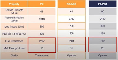
One effective way to improve the flow of amorphous polymers is by alloying them with semi-crystalline polymers. In Table 1 the example of Polycarbonate is shown which is alloyed with ABS and PBT. 

Table 1: Blending PC with ABS and PBT to improve flow and chemical resistance

PC itself has good all over mechanical values and excellent impact behavior. However, fuel resistance is poor and also injection moulding is more challenging. Alloying a PC with ABS results in a material which has better flow properties. Fuel resistance remains at the same bad level. Alloying PC with PBT we can improve both: lifting fuel resistance to a fair level and double the melt flow. You have the toughness of a PC combined with the solvent resistance of PBT. Your product will have good heat, chemical, and impact resistance with good mouldability. 

Why are polymer blends useful during the material selection process?

Polymer blends help to fulfill open product requirements since most polymers show a lack of certain properties (flexibility, transparency, low density). Also, lower material costs can be achieved with polymer blends. 

Thanks for reading and #findoutaboutplastics

Greetings, 

Herwig 

Interested to talk with me about your polymer material selection, sustainability, and part design needs - here you can contact me 

Subscribe to my Polymer Material Selection book launch page 

Interested in my monthly blog posts – then subscribe here and receive my high performance polymers knowledge matrix.

Literature: 

[1] https://www.youtube.com/watch?v=nLGcSszTaTs

[2] https://www.youtube.com/watch?v=QrbHcEagUZM


Saturday, 29 October 2022

The Important Role of Additives: Enhancing Polymer Properties for High Performance Applications (Part 2)

Hello and welcome to a new post. Today we continue with the second part of our plastic additives series. In this post we discuss how fillers change the properties of polymer compounds and how we can use this during material selection

Here you can read part 1.

General effects caused by fillers

Table 1 shows the effects on Elastic-modulus, elongation, toughness, flames resistance, and dimensional stability caused by different fillers such as glass fibers, UV-stabilizers, and flame retardants. UV-stabilizers, flame retardants (organic and inorganic), and anti-statics show a negative impact on the modulus of elasticity, elongation and toughness. 

Table 1: overview of effects caused by different additives [adapted from 2]

Modification of properties by using isotropic, flaky, and fiber shape additives

Now with the know-how of Table 1 it is possible to influence certain properties by using different additive geometries. In general, isotropic fillers have the same behavior in x-, y-, and z-direction and improve the dimensional stability of your final part. Platy shaped fillers are very good in the x- and y-direction however not so good in z-direction. Fibers are only good in one direction and show a fair behavior in the remaining two. 

Table 2: overview of property modification by filler geometry [3]

Example on warpage control of semi-crystalline polymers

In Table 1 and Table 2 we discussed how to improve the dimensional stability of polymers. In this example we have semi-crystalline polymer with a glass fiber loading and we would like to have a better hand on the warpage control of the final part. The glass fiber loading causes a different shrink rate in x-direction than in y-direction leading to warping of the part. If we take a semi-crystalline polymer with isotropic filler loading, shrink rate in x- and y-direction are the same, however the final part will show a low strength. The key is to combine glass fibers with isotropic filler in order to obtain a flat part with good strength properties. 

How to do it? 

A common compounding solution is to use 15 weight-% glass fiber and combine it with 25 weight-% mineral or beads. 

Example improvement of wear resistance of amorphous polymers

In case you consider an amorphous polymer such as Polycarbonate (PC) for applications which need to have a certain level of wear resistance (for example gears), an effective way is to use PTFE as a lubrication additive. This is demonstrated in Table 3, where 15 weight-% PTFE is added to a PC. Both, the wear factor and the dynamic coefficient of friction could be reduced. 

Table 3: wear improvement of amorphous polymers

Example Polyamide 6.6 (PA 6.6): filler vs. reinforcement

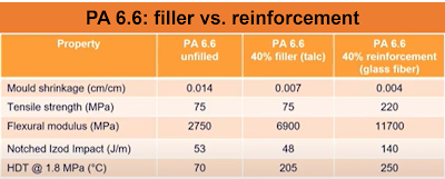
In general, by using fillers we can have a good shrink control, improve the modulus of elasticity, and heat distortion. Impact resistance will decrease and strength will remain the same. Using reinforcements, strength and modulus will improve, together with heat distortion. Regarding impact resistance, reinforcements will make brittle resins tough and tough resins brittle. Table 4 compares an unfilled PA 6.6 with a 40 weight-% talc filled and a 40 weight-% glass fiber reinforced PA 6.6 to better illustrate the main differences of filler and reinforcement. 

Table 4: PA 6.6 - filler vs. reinforcement

Example POM (Acetal): filler vs. reinforcement

In the next example we have an unfilled POM homopolymer (Table 5) and glass as filler and reinforcement. Filling the POM will increase the tensile modulus, however tensile strength will decrease. Reinforcing with glass by using a proper sizing of the glass which can be coupled to the polymer, tensile strength and modulus can be increased. 

Table 5: POM - filler vs. reinforcement

In the next part we discuss how to improve the conductivity (thermal and electrical) of polymers. 

Here you can jump to part 1 and here to my posts on flame retardants, as well as CTI improvement strategies, involving additives. 

Thanks and #findoutaboutplastics

Greetings, 

Herwig 

Interested to talk with me about your polymer material selection, sustainability, and part design needs - here you can contact me 

Subscribe to my Polymer Material Selection book launch page 

Interested in my monthly blog posts – then subscribe here and receive my high performance polymers knowledge matrix.

New to my Find Out About Plastics Blog – check out the start here section

Literature: 

[1] Gächter and Müller: Plastics Additives

[2] DuPont and Biesterfeld Interowa - Design with plastics, 2011

[3] Chris DeArmitt: https://phantomplastics.com/plastic-materials-training-from-a-top-expert/learn-about-filled-plastics/

[4] https://youtu.be/h7iUC9-JdiU

[5] https://youtu.be/nLGcSszTaTs

[6] https://www.youtube.com/watch?v=1pPx1YbGDBA


Thursday, 27 October 2022

Processing of Engineering Thermoplastics: PBT and its crystallization behavior

Hello and welcome to a new post. Today we discuss considerations for injection moulding of Polybutylene terephthalate (PBT). In previous posts we discussed the DMA behavior of PBT and other thermal properties.  

General properties of PBT

PBT belongs, together with PET, to the class of Polyesters. Polyesters are made by polycondensation reaction under the release of water. Unreinforced PBT can be used from -60°C up to +110°C and reinforced PBT up to +200°C. In case PBT is exposed to hot water above 60°C it shows hydrolysis reactions (degradation reaction). It has good electrical properties such as electrical breakdown strength / dielectric strength at higher temperature (aliphatic Polyamides show much lower dielectric strength at higher temperature). Also the Comparative Tracking Index (CTI) is high with PBT and therefore it is often used in electrical and electronics applications (housings, connectors, busbars, e-Mobility). PBT has good mechanical and stress cracking properties. It burns with yellow-orange sooty flame. It needs to be protected against UV and to reach a certain flame classification, flame retardants need to be added. 

Injection moulding of PBT: Dos and don'ts

Drying before moulding: min. 3 hours at 120°C; this ensures optimal mechanical properties in your final part at a later stage. Remaining humidity should be not more than 0.04%. If there is 0.1% humidity left, tensile strength may be reduced up to 12% from the optimum value. I created a table with the different maximum moisture levels after resin drying to ensure proper processing of 36 polymers.

Residence time: max. 8 to 10 min, otherwise material degradation will take place; thin wall parts optimal residence time is around 5 minutes and for thick wall parts around 3 minutes; if you are around 1 to 2 minutes, risk is given that there are not molten plastic pellets. 

Packing: long packing is beneficial to prevent shrinkage cavities. 

Injection speed: as high as possible, especially for thin wall parts. 

Tool temperatures: PBT needs lower tool temperatures due to the high crystallization rate of the polymer. Mould temperatures between 30-60°C are sufficient.  If you produce precision parts, mould temperatures up to 120°C are better, since the post shrinkage will be negligibly small. 

Post shrinkage: low mould temperatures up to 0.3% and with high tool temperatures between 0.01 and 0.022%.

Melt temperatures: In table 1 an overview on the different processing temperatures is given.

Table 1: PBT processing temperatures

Conclusions

During the design and material selection phase, polymers are selected due to their specific properties which they can bring to the table. However, if certain things such as proper drying before processing, crystallization rate and residence time during processing are not considered, the final part will not have the desired optimum properties. 

Thanks for reading and #findoutaboutplastics

Greetings, 

Herwig 

Interested to talk with me about your polymer material selection, sustainability, and part design needs - here you can contact me 

Subscribe to my Polymer Material Selection book launch page 

Interested in my monthly blog posts – then subscribe here and receive my high performance polymers knowledge matrix.

New to my Find Out About Plastics Blog – check out the start here section

Literature: 

[1] http://www.kunststoff-meister.de/mediapool/132/1320009/data/PBT.pdf

[2] https://www.plastverarbeiter.de/wp-content/uploads/migrated/docs/348_27934.pdf


Tuesday, 11 October 2022

The Important Role of Additives: Enhancing Polymer Properties for High Performance Applications (Part 1)

Hello and welcome to a new blog post. Today’s topic is the important role of polymer additives and since it is a broad topic I will split it into several parts.

Part 2

Part 3

In the first part we discuss the types of additives and things to consider when you use additives in material- and application development.  Having a basic understanding of fillers and what they can enable in a plastic compound is important for polymer material selection too. 

What can additives do for your polymer?

The limited usage range of certain polymers can be improved by incorporating additives into the polymers. Thinking of polyolefins, without adding antioxidants, not even processing would be possible in a proper way. Another example is rigid PVC which can be made flexible by adding plasticizes. Adding glass fibers to Polyamide 6 increases the heat distortion temperature (HDT), as well as strength and stiffness. Using color pigments allows the PC to be moulded in several colors and PP can be made radiation stable by adding free radical scavengers. Conductive fillers turn polymers from an isolator to a material which can be used as a heat sink. Another example is the chemical compound Piperine which is responsible for the spicy appearance of black pepper. It is added during fuel line extrusion for cars to prevent biting of cables due to animals. If they bite, it will start hurting and they will immediately stop. 

Additives can turn brittle polymers such as Polystyrene into a toughened polymer by using impact modifiers. Also can additives improve processing, dimensional stability, and strength. Furthermore, they can improve thermal, radiation, and light stability. They are able to improve the flame retardant level and turn for example Polyesters flame retardant and improve long-term aging, scratch resistance, aesthetics, and biocompatibility.  Another example is that additives can improve electrical properties such as the Comparative Tracking Index (CTI)

Polymer material performance: the effects of additives in an overview

Table 1 shows the different additive classes and their effect in the final plastic compound. Flame retardant additives we discussed previously already here

Table 1: Overiew of different additive classes and their effect in the final plastic compound.

What do we need to consider when we use additives? 

The different effects of various additives on the final compound need to be considered by the formulators. Physical and chemical properties, toxicity, sterilization as well as biocompatibility (in case of health care applications) must be evaluated. Also checking the shelf life of the new material compound needs to be considered since the used additive may cause some side reactions which lead to a decrease in properties. 

In the next part we discuss how to modify the properties of compounds by using different shaped fillers. 

Thanks and #findoutaboutplastics

Greetings, 

Herwig 

Interested to talk with me about your polymer material selection, sustainability, and part design needs - here you can contact me 

Subscribe to my Polymer Material Selection book launch page 

Interested in my monthly blog posts – then subscribe here and receive my high performance polymers knowledge matrix.

Literature:

[1] Gächter and Müller: Plastics Additives

[2] Sastri - Plastics in Medical Devices: Properties, Requirements, and Applications


Sunday, 25 September 2022

How To Turn Thermoplastics Carbon Neutral Or Even Carbon Negative? Here Is An Effective Way

Hello and welcome to a new blog post. Today we are going to discuss how to turn thermoplastics carbon negative in an effective way. 

In previous posts I presented to you the Global Warming Potential (GWP) of different plastics vs. their density as well as the GWP values of thermoplastics compared to their different thermal properties and transitions: Tg, heat capacity (Cp), short term temperature exposure (HDT) and long term temperature exposure (UL Yellow Card).

Among the materials and chemicals, thermoplastics have already a low GWP value. Gasses such as methane (CH4) have an estimated GWP of 27-30 over 100 years, and the average cement has a GWP of 600-800  kg CO2 eq / ton. Most thermoplastics are in the range of 2 -8 kg CO2 eq / ton. 

Is it possible to have carbon negative thermoplastics?

Yes, by using specific functional fillers which are able to lock in more carbon dioxide than they release in a later stage. In the following we discuss two filler examples: biochar and hemp. In general, after the pyrolysis of biomass, biochar is the lightweight black residue and it consists out of carbon and ashes.

Biochar

Seth Kane [2] and his team demonstrated that carbon-neutral composite materials can be produced by adding biochar. They evaluated  it over a cradle-to-gate life cycle assessment. Biochar was added as a filler in recycled HDPE (rHDPE), virgin HDPE, bio-based polylactic acid (PLA), and polyhydroxybutyrate (PHB).  In general, biochar fillers lock carbon in a stable form and this in a permanent way. Key results were that 40 w% biochar filler is sufficient for rHDPE to reach 0 kg CO2 equivalent. PLA requires 50 w% biochar filler to be considered 0 kg CO2 equivalent. And HDPE needs 52 w% to reach carbon neutrality (Figure 1). Furthermore they found out that biochar increases the tensile strength of rHDPE by 45%, and stiffness by 126%. Also the flexural storage modulus could be improved by 79% however all over the compound was more brittle. They concluded that adding biochar linearly reduced the GWP potential of the examined plastics by up to 3.3 kg CO2 equivalent per kg of material compound. 

Figure 1: Overview polymers with biochar filler to reach 0 kg CO2 eq. GWP

Hemp

In a similar situation we have hemp as a filler. It can be used with PP as base polymer in Automotive applications (door panels, seat backs paneling, bumpers, spoilers). Apart from cost and weight reduction, using hemp additives reduces the carbon footprint too. Industrial hemp additive manufacturer Heartland [4] demonstrated a carbon footprint reduction of virgin plastics by as much as 44%. 

Conclusions

Biochar and hemp used as fillers in thermoplastics are an effective way to reduce the carbon footprint. Together with recycling of thermoplastics (including fillers, and compounds) as well as other mitigation strategies such as bio-based plastics, usage of renewable energy in plastics manufacturing will reinforce the advantage of plastics over other so-called green materials in the long run. 

Greetings and #findoutaboutplastics

Herwig 

Interested to talk with me about your polymer material selection, sustainability, and part design needs - here you can contact me 

Subscribe to my Polymer Material Selection book launch page 

Interested in my monthly blog posts – then subscribe here and receive my high performance polymers knowledge matrix.

New to my Find Out About Plastics Blog – check out the start here section

Literature: 

[1] https://www.madeofair.com/

[2] https://www.sciencedirect.com/science/article/pii/S2666682022000226#sec0007

[3] https://www.sciencedirect.com/science/article/pii/S0959652620338956

[4] https://www.businesswire.com/news/home/20220124005281/en/Heartland-and-Ravago-Develop-Products-to-Reduce-the-Carbon-Footprint-of-Plastic

[5] https://www.researchgate.net/figure/Global-warming-potential-GWP-range-for-cementitious-Environmental-Product-Declarations_fig3_341943113

[6] https://www.findoutaboutplastics.com/2022/02/design-data-for-plastics-engineering.html


Tuesday, 20 September 2022

Flame Retardant Classifications According DIN EN ISO 1043-4 - What do they mean?

Hello and welcome to a new blog post. In a previous post we discussed flame retardants in a general way, followed by examples of flame retardants for Polyamides. In this post we uncover the flame retardant classification according to DIN EN ISO 1043-4.

Example of a part marking code with flame retardant

Let us begin with an example and let us decode it step-by step: PE-LD FR (30+40) 

PE-LD: Polyethylene with low density

FR (30+40): contains flame retardant form classification 30 and 40

What does the classification FR(30+40) mean?

To find out we need to have a look into the DIN EN ISO 1043-4 where we can find the different flame retardant types. 

Figure 1 shows an extract of the most common flame retardant classes. We can distinguish between halogen compounds, nitrogen compounds, halogen-free organophosphorus compounds,inorganic phosphorus compounds, metal oxides, Boron and zinc compounds, silicon compounds, and graphite.

Figure 1: extract of the most common flame retardant classes according DIN EN ISO 1043-4

Cycling back to our example, we can state that this PE-LD uses nitrogen compounds (3) and halogen-free organophosphorus compounds (40) as flame retardants.

In case you want to overmould copper (busbar application) with a Polyamide which needs a certain flame retardant level, attention should be given to use flame retardants from classification 40. Such flame retardants do not create electrical corrosion on your part which in turn can cause a short circuit. 

In market segments such as automotive, more and more flame retardant material in combination with other properties like thermal conductivity are used. Using Figure 1 during material selection can help to prevent part failure in the long run for example due to electrical corrosion (migration of flame retardants on surface). 

Thank you for reading and #findoutaboutplastics

Greetings, 

Herwig 

Interested to talk with me about your polymer material selection, sustainability, and part design needs - here you can contact me 

Subscribe to my Polymer Material Selection book launch page 

Interested in my monthly blog posts – then subscribe here and receive my high performance polymers knowledge matrix.

New to my Find Out About Plastics Blog – check out the start here section

Literature:

[1] https://www.findoutaboutplastics.com/2022/06/flame-retardants-why-do-we-need-them.html

[2] https://webstore.ansi.org/Standards/DIN/dineniso10432016-1640336

[3] https://www.wikiwand.com/de/ISO_1043

[4] https://plastics-rubber.basf.com/global/en/performance_polymers.html